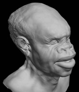
-import obj
- apply a meshsmooth modifier to the object
- aplly a vray displacement modifier
set an amount of 8 and a shift of -4
resolution to 1024
render in 720 576 in 9 sec

ZB test

Another vray test.
The displacement values here are
13.344 with -6.672 shift
These values are based on the displacment value given by pixolator and the autoscale value in the OBJ (use a text editor to open the file, it is in the header), there should be no need to guess this. I'll put up a zscript/maxscript combination to do all this automatically once I have put a simple interface on it.

ZBtest

3DS MAX, Scanline - nimajneb
OBJ file to Editable Mesh.
Meshsmooth, 1 Iteration
Collapse to EMesh
Set Sub-D Displacement, Medium Preset (High Kills it, on my box)
Set material Bump and Displace same map (instanced). Set level to 100, and instead, change output to remap iamge from -.5 to .5. Set overall output to taste (I did the reciprocal of .834, 1.2 approx).
45 sec to render.

ZBtest2

Max 6 + Mental Ray - Zeddicus
- Displacement map flipped vertically and resaved in Photoshop as 16-bit RGB TIF file, no compression, no color management applied or embedded profile.
- Map loaded into material editor slot as bitmap, blur 0.01 (doesn't seem to matter with MR which ignores it, but good habit anyways to prevent banding if you use another renderer such as Vray), RGB offset -0.5 (map will look black, but it's not really and negative displacement is still there). By the way, if you didn't flip the map in Photoshop, set V tiling to -1.0 so that it renders properly.
- Using a second slot in the material editor, I applied a standard material with mental ray displacement shader unlocked (see heading mental ray Connection near bottom) and displacement map instanced as the extrusion map. Object Independant: checked / Displacement Length: 1.0 / Extrusion strength: 12.0 / the rest at default.
- For render options - View: Checked / Edge Length: 1.0 (higher speeds thing up but lowers render quality, lower setting slows things down but improves render quality) / Max Displace: 15.0 / Max Level: 6 (play around for best speed to render quality ratio)
Note: If you get a log error about your displacement map, make sure it's a proper 16-bit RGB TIF as stated above. 16-bit greyscale works, but gets converted to RAW and also is more likely to show banding.
The render posted previously in this thread (render time 1:40 at 640x480 / default render settings used except for those that were displacement related / two omni lights using shadow mapping):

ZBTEST3

心得 - mangriff
Yay!! I finally figured out how to get really good displacement maps in MAX!!! With default scanline settings. It works great, animates great, looks great and is faster than SH$$$$ yay!! Oh excuse me i have been struggling with this for the past few days sans sleep, food, blah blah blah. Cool, well here is the pic! PLEASE if anyone has questions ask me and id love to share the steps and settings! ooooOOooooweeeEEEEEEEE!!
First things first. DISABLE displacement in the render dialog! Everytime i forget about that the system crashes and poop pours out of every drive like a toilet rebelion. But seriously i got the best results both in control and results using the modifiers only. So import the mesh. Add turbo smooth with the iterations in the render so that the view port isn't bogged down with the smoothing. You can put on like 1 or 2 iters in the viewport just to see and judge how it's all going, and then put like 4 or if you can 5 in the render dialog for the final deal. Open the material editor and apply an open material to the mesh. In the material's displacement map import the tif file. You can import the file in any map slot because we are not using the displacement of the actual material, but we need to adjust the tiling so you can't just load in the image as an image. If you want you can just change the material slot to be a 2d map only and reference that, but since i figure you would want to a "3d" material on the guy anyway eventually it works to just bring it in the in displacement slot (that is the use after all). ANYWAY, change the V tiling to -1 instead of 1. because the map is flipped around the V axis. Now the map is ready to be applied to the mesh. Next you add the displace modifier in the stack and adjust the strength spinner. Make sure you turn on the luminance center and leave it at .5 (this makes it so that the mesh doesn't inflate completely and basically sets 50% grey to be the default condition, so white will protrude and black will recess which is what we want). under image, choose "MAP" and when the map chooser pops up find the image in the MTL Editor "browse from" choice. This uses the map that we inverted along the V for the displacement. The mesh should deform, if not then you may need to up the strength a bit. That's it. I made a morph target to show that the low poly version can be used to deform the high poly form for animation or posing. Lighting is just a couple omni lights that i rigged in the traditional 3 pt lighting theory. That's about it i think, let me know if something doesn't make sense and/or if this works for you! Later
有關於alpha depth factor 的解說 ~ 超棒!
沒有留言:
張貼留言